DIN EN ISO 10628 in practice: what the standard actually requires
The DIN EN ISO 10628 standard governs the content, presentation, and symbols used in process flow diagrams. What does that mean in day-to-day work? A practical guide for process engineers, plant constructors, and anyone creating or reviewing P&ID diagrams.
Anyone creating a P&ID that needs to stand up in practice—during acceptance, an audit, or handover to an operator—cannot avoid DIN EN ISO 10628. But what does this standard actually say, and what does it mean for everyday work?
What the standard governs
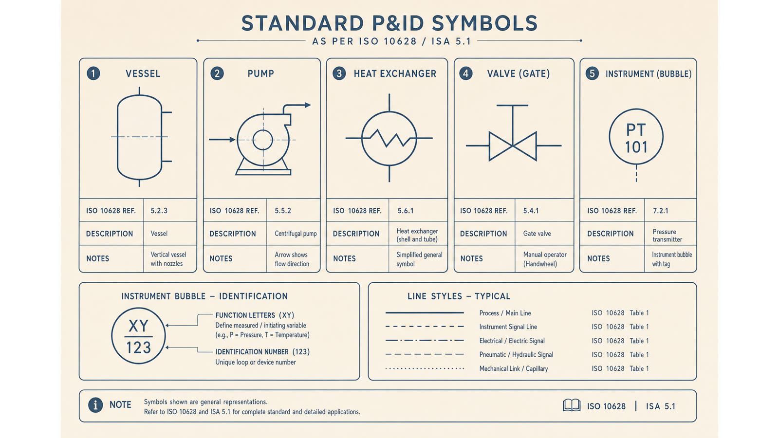
The standard consists of several parts. Part 1 (DIN EN ISO 10628-1) describes the general rules for flow diagrams of process plants. Part 2 (DIN EN ISO 10628-2) defines the graphical symbols—from equipment and vessels to pumps and heat exchangers, valves, and measuring points. Further parts cover special cases.
In practical terms, this means that anyone drawing a pump should use the standardised symbol rather than an invented shape. Anyone depicting a heat exchanger has a defined selection of representations. This creates clarity across sites, suppliers, and generations.
Three levels of detail
The standard distinguishes three levels, depending on the purpose of the diagram:
- Block flow diagram—shows the process principle with main components and material flows
- Process flow diagram—supplemented with quantities, pressures, temperatures, and energy flows
- P&ID—the complete engineering document with measurement, control and regulation technology, piping, valves, and tag numbering
The required level depends on the recipient. For a process description in a scientific publication, the block flow diagram is often sufficient. For awarding a contract to a plant constructor, a P&ID is required.
Tag numbers and identification
Every component receives a unique identifier: the tag number. It typically follows a scheme consisting of a functional abbreviation, equipment number, and, where applicable, location. Example: P-101 for the first pump in plant section 100. The tag number links the diagram to the bill of materials, the data sheet, and later in operation to the asset-management system.
piblaster numbers equipment automatically according to common schemes. You can override the scheme, but you do not have to maintain it yourself. Anyone who has searched after an audit for why the same pump was called P-101 once and P101 another time knows the value of this.
What is checked in an audit
During audits—such as those under GMP, ATEX, or plant-specific regulations—the P&ID is used as a central document. The usual checks include:
- Consistency between the diagram, bill of materials, and data sheets
- Use of standardised symbols in accordance with DIN EN ISO 10628-2
- Unique tag numbers, with no duplicates
- Complete capture of measurement, control, and regulation technology
- Currency—the revision status and date are identifiable
Those using a specialist tool that covers these points will have significantly less to discuss in an audit. The standard lives through details—and the details become visible in the PDF export.
Conclusion
DIN EN ISO 10628 is not bureaucratic self-interest. It is the shared language used by process engineers, plant constructors, and operators. Anyone creating a standard-compliant P&ID avoids follow-up questions, rework, and, in the worst case, repeating an acceptance test.